Printed camera drone
Printed plastic is roughly 14 times softer than carbon. Can a sub-250 g printed frame still fly and film cleanly?
- Period
- 2026 to present
- Revision
- 09 Nov 2026
- Status
- In design
- Stack
- Fusion 360, Python, ArduPilot, PAHT-CF, PLA-CF, TPU
- Takeoff weight
- 248g
- modelledLimit 249 g for the EU A1 category
- First frame mode
- 194Hz
- simulatedUp from 107 Hz in v2d, Fusion modal study
- Hover power
- 32.5W
- modelledPropulsion model, 5.1 inch props
Problem
Below 250 g there is no room for a gimbal. The camera is bolted to the frame and sees every vibration the frame carries.
Printed plastic is much less stiff than carbon, which hurts in two places. Vibration leaks into the flight controller’s gyro, so the control loop reacts to noise and the drone flies twitchy. The same vibration shows up in the video as rolling-shutter wobble, which software stabilisation cannot fully remove.
Claim to prove: a 3D-printed sub-250 g camera drone can fly and film as cleanly as a carbon-frame one. If it holds, a drone can be redesigned and reprinted for each job, which makes cheap, custom aerial filming practical.
The end use is a GPS follow drone that films me while I cycle.
Approach
Five layers attack the vibration at different points between the propeller and the camera. Each layer is switched on separately and compared against the one before it.
- Stiff frame: hollow box-section arms welded into a closed battery-box core, with the arm modes placed above the full motor speed range.
- Flight controller isolation: soft mount on grommets, compared in gyro logs.
- Filtering: an ArduPilot harmonic notch that follows motor speed (bidirectional DShot), covering the first and second harmonics.
- Frame v3: a generative-design frame, fed with the tap-test and flight-log data from v2.
- Camera mount: a rigid bracket plus a tuned TPU isolator near 40 Hz.
The flight controller is the sensor. Its gyro logs at high rate to an SD card, so the vibration tests need no extra measuring hardware.
The isolator stiffness follows from the camera mass and the target frequency. Halve the frequency and the spring must be four times softer.
Current status
Frame v2e is designed and simulated. It is prepared for a first test print in PLA-CF at the university lab, which has nearly the same stiffness as the final PAHT-CF (3700 against 3640 MPa) and prints far more easily. Parts are being ordered. First flights come after that, and the final comparison is targeted for the start of summer semester 2027.
This is my first drone build.
Next steps
- Print frame v2e in PLA-CF and run a free-free tap test, with the FFT in Python, targeting agreement with the Fusion model within about 10 percent.
- Flight tests with ArduPilot high-rate logging at hover, cruise and full throttle.
- Calibrate the Fusion model against the logged data, optimise the shape, and print the final frame in CF nylon under 249 g.
Figure 1
Keep the frame out of the motors' way
Each bar is a modal frequency from the Fusion study. The shaded bands are what the propellers push into the frame. Moving the first mode from 107 Hz to 194 Hz takes it clear of hover.
Figure 2
Where the frame bends
Fusion mode shapes for the same frame at three stages. Red is the most movement, blue the least.
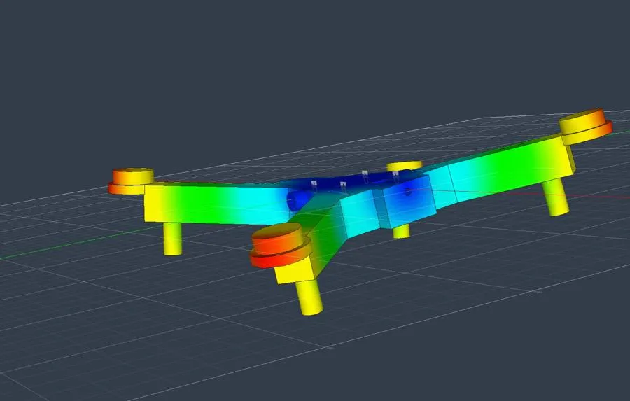
The open tray twists, right on the hover band.
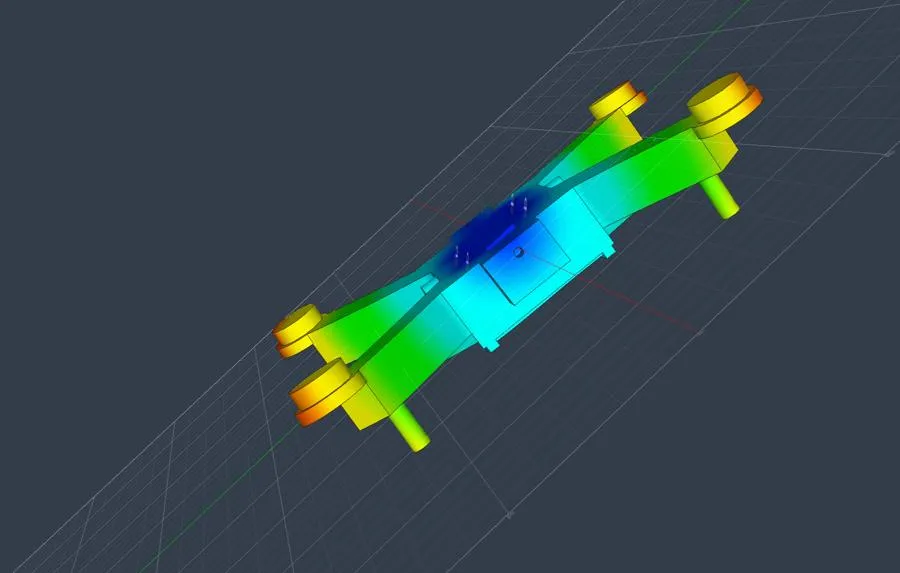
The core stays rigid and only the arms bend.
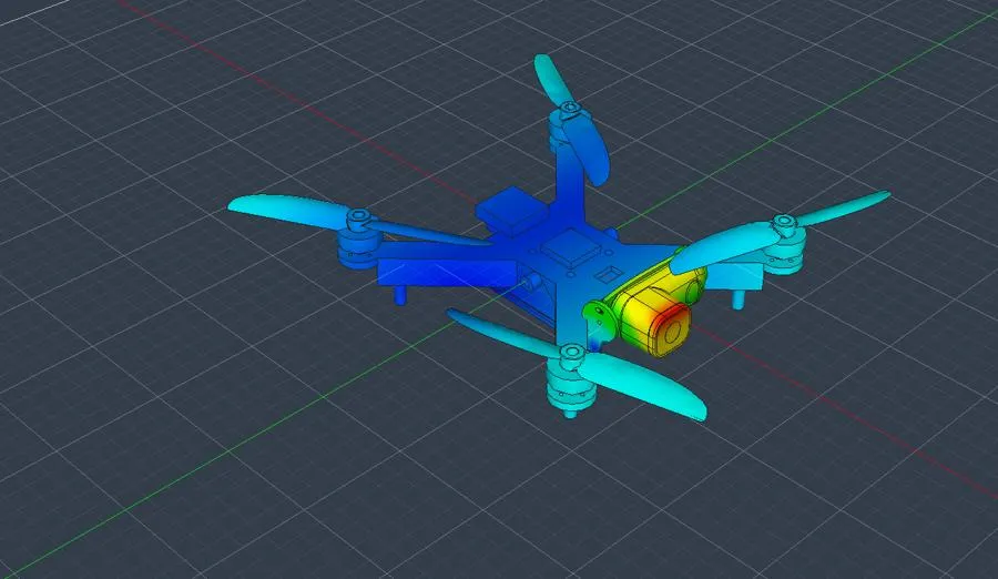
The camera mount swings near hover. This is the next fix.
Figure 3
Six frames, one lesson at a time
Each version answers a problem the previous one showed. The parametric Fusion script makes every change a single number.
- v1
Solid rib arms
Arm mode 198 Hz
4 inch props, 6 x 10 mm solid arms, about 23 g. The arm mode sat right on the hover motor frequency.
Lesson: Design for stiffness and frequency, not strength.
- v2
Hollow box arms
Arm modes about 384 Hz
12 x 14 x 1.6 mm hollow boxes, about 34 g. Material far from the neutral axis makes the arm much stiffer for the same mass.
- v2b
Efficiency layout
About +9% flight time
Moved to 5.1 inch Gemfan LR5126 props on F1404 2900KV motors, chosen with a propulsion model built from T-Motor bench data. The whole rpm range (0 to 209 Hz) now sits below the arm modes.
- v2c
Battery-tray core
72 x 46 mm core
Plate plus a 16 mm rim wall acts as a box-section core with the arms welded into it. Heat-set inserts for the flight controller, tuning-rig pivots at CG height.
- v2dProblem found
Low camera
First mode 107 Hz
Camera tilted 25 degrees down in a TPU cradle to keep props out of shot. The Fusion modal study then found the open-bottom tray twisting at 107 Hz, right on hover.
- v2eCurrent
Closed battery box
First mode 194 Hz
Deeper tray closed by a 1.1 mm sliding lid in side rails, keel webs under the arm roots. The lid is structural: without it the frame mode falls back into the cruise 2x band.
Figure 4